Fatigue Analysis
Fatigue analysis is the process of determining how a mechanical system will withstand cyclic loading over time. It is vital for ensuring the reliability and durability of parts that experience repeated or fluctuating loads.
A fatigue analysis involves:
- Determine the cyclic loading – Identify the type of cyclic loads the part will see in use, including magnitude, frequency, waveform, and any other characteristics. This includes loads from vibration, impact forces, inertia loads, etc.
- Calculate stress range – Calculate the minimum and maximum stresses the part will experience under the cyclic loading. The stress range is the difference between these values.
- Determine stress concentration factors – Account for any stress raisers in the part design that could lead to premature fatigue failure. Stress concentration factors quantify the local stress increase.
- Construct a stress-life (S-N) curve – Plot the part’s materials’ resistance to cyclic stresses at different life levels. This shows the number of cycles to failure at each stress range.
- Determine a fatigue limit – Some materials have an upper-stress range below which they can withstand an infinite number of load cycles without failure. This is known as the fatigue limit.
- Apply a safety factor – Apply an appropriate safety factor to the fatigue analysis results to account for uncertainties and ensure adequate durability.
- Consider environmental effects – Aggressive environments can significantly reduce fatigue life. Harsh conditions may require a higher safety factor.
- Perform a fracture mechanics analysis – For parts with existing cracks or flaws, fracture mechanics methods are needed to determine fatigue crack growth rates.
The fatigue analysis aims to determine if a part can withstand the expected number of load cycles over its intended lifetime and identify areas that are fatigued early. The results can be used to redesign parts for improved fatigue life and durability.
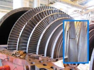
Fatigue failure tends to occur without warning, so engineers rely on fatigue analysis to avoid potentially catastrophic failures due to cyclic loading. A proper analysis considers all relevant fatigue factors to ensure conservative and reliable results.

Fatigue behavior is generally of three forms: (1) High Cycle Fatigue, (2) Low Cycle Fatigue, and (3) Thermomechanical Fatigue. The main difference between high-cycle fatigue (HCF) and low-cycle fatigue (LCF) is that in high-cycle fatigue, low-amplitude and high-frequency loads lead to elastic strains. Still, in low-cycle fatigue, high-amplitude loads and The frequency is low, which leads to plastic strains.
Low Cycle Fatigue
 Low Cycle Fatigue (LCF) is a type of fatigue in which the material life is less than 10,000 cycles. To test this fatigue, loading is done in the form of strain control. Loading in this type of fatigue is high amplitude and low frequency, which leads to plastic strains in it. There are three steps to consider when testing for low cycle fatigue:
- Crack formation in the specimen
- Crack growth in the sample
- Final sample failure (the damaged sample can be read using the SEM technique for more information).
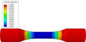
Simulating low-cycle fatigue is a topic that has grown significantly in recent years. This type of fatigue is well simulated in a variety of finite element software. Prediction of damage, crack growth, and final failure has worked well for a variety of parts with complex geometry and different materials in these applications.
High Cycle Fatigue
High Cycle Fatigue (HCF) is a type of fatigue in which the number of cycles leads to the failure of a part of more than 10,000 cycles and the test usually continues until the final failure of the sample. Loading this type of fatigue is done with stress control. By performing several tests and recording the results, the S-N diagram is produced. The S-N diagram is the relationship between stress level and material fatigue life under material service conditions. In addition to performing a variety of cyclic fatigue tests, the company has developed several finite element programs to predict the life of composite and foam parts. The ASTM E466 standard covers the terms and conditions for performing axial cycle fatigue testing for metallic materials.
Fatigue Test Consideration
To plot the S-N diagram, the sample is subjected to a fatigue test with a load of more than 10 million (10.0e + 6) cycles to determine its endurance limit or fatigue strength. This test may take days or weeks. For this reason, the holding cycle is often applied at a higher frequency to reduce the test time. For metallic materials, the ASTM E466 standard recommends frequencies between 0.01 and 100 Hz. If the loading frequency is high, the temperature of the sample will increase and surrender may occur in an area of the sample, which may be an indication of the maximum loading frequency of the material. In contrast, polymers and plastics are more affected by temperature rise due to the effects of hysteresis. This combines with their low melting point and results in lower fatigue strength in high-frequency tests. Polymers and plastics are usually tested at 5 Hz.
Fatigue Test Standards
Here are some common international standards for performing fatigue tests:
- ASTM E466 – Standard Practice for Conducting Force Controlled Constant Amplitude Axial Fatigue Tests of Metallic Materials. Covers procedures for performing constant amplitude axial fatigue testing of metals.
- ASTM E647 – Standard Test Method for Measurement of Fatigue Crack Growth Rates. Specifies procedures for conducting fatigue crack growth rate measurements on metallic materials.
- ASTM E739 – Standard Practice for Statistical Analysis of Linear or Linearized Stress-Life (S-N) and Strain-Life (ε-N) Fatigue Data. Provides guidance on statistically analyzing fatigue test data to generate S-N or ε-N curves.
- ASTM E1049 – Standard Practices for Cycle Counting in Fatigue Analysis. Specifies methods for accumulating and analyzing variable amplitude fatigue test data, including cycle counting techniques.
- ISO 12107 – Metallic Materials — Fatigue Testing — Statistical Planning and Analysis of Data. Similar to ASTM E739, provides statistical methods for evaluating fatigue test results for metallic materials.
- ISO 12106 – Metallic Materials — Fatigue Testing — Axial Force Controlled Method. Comparable to ASTM E466, specifies procedures for axial fatigue testing of metals under force control.
- BS 7448 – Fatigue and fracture testing of metallic materials. A British Standard covering standard practices for both constant life and variable amplitude fatigue testing of metals.
- DIN 50308 – Testing of metallic materials; fatigue testing; general principles for planning, performance, and evaluation of fatigue tests. A German standard that outlines general principles for conducting fatigue tests and analyzing results.
Fatigue Design & Analysis
Here are some key international standards for fatigue design & analysis in engineering applications:
- DNV-RP-C203 – Fatigue Design of Offshore Steel Structures – is a recommended practice issued by Det Norske Veritas (DNV), a marine classification society. The fatigue design is split into two failure modes: crack initiation and crack propagation. The recommended practice provides methods for designing for both modes.
- ASME B&PV Code, Section III – Rules for Construction of Nuclear Facility Components. Contains Subsection NH which provides guidance for the fatigue analysis and design of nuclear components under cyclic loads.
- ISO 12107 – Metallic materials – Fatigue testing – Statistical planning and analysis of data. Specifies statistical methods for evaluating fatigue test data of metals to determine fatigue properties. Used as an input for fatigue design.
- ISO 12106 – Metallic materials – Fatigue testing – Axial staged force controlled method. Defines procedures for constant amplitude axial fatigue testing of metals to generate fatigue data.
- ISO 12991 – Bearings – Remanufacturability – Terms, definitions, and testing methods. Includes methods for fatigue testing of remanufactured bearings to verify performance.
- ASME B46.1 – Surface Texture. Covers the measurement and specification of surface roughness which impacts the fatigue life of parts. Surface finish is considered in fatigue design.
- AWS D1.1 – Structural Welding Code – Steel. Provides requirements for welding procedures and qualifications that minimize fatigue risks due to weldments.
- BS 7608 – Guide to fatigue design and assessment of steel products. British Standard outlines procedures for the fatigue design and assessment of steel structures and components.
- IIW Recommendations – Fatigue design of welded joints and components. Publishing of the International Institute of Welding that covers the fatigue assessment of welded joints.
Services
- FEA simulation of fatigue analysis 1
- Writing user subroutines for damage & fatigue material models in Abaqus 1
- Generating Abaqus plugin for fatigue analysis automation 1
- Design-by-analysis
- Fatigue analysis training 1 2


