abaqus, Abaqus Tips & Tricks, Abaqus Tutorials

FRP Composite Failure Criteria & its Damage Evolution – Abaqus & LS-Dyna

FRP Composite Failure Criteria

FRP Composite Failure Criteria & its Damage Evolution

When we come to the finite element failure analysis in Fibre Polymer Laminates, choosing the appropriate criteria and material model to predict failure and damage is the first question that comes to mind. Does this criterion have the ability to correctly predict damage and failure in the FRP composite? How to determine its constants? Which of the failure criteria has better accuracy? How about damage evolution? Etc.

The difficulty of the work can be understood from the fact that according to the definition of  the International Association for the Engineering Modelling, Analysis and Simulation Community (NAFEMS):

There is no universal definition for what constitutes the ‘failure’ of a composite.

However, according to the vocabulary of failure engineering, this is how it is defined:
‘Failure’ is the point beyond which the structure or component ceases to fulfill its function.

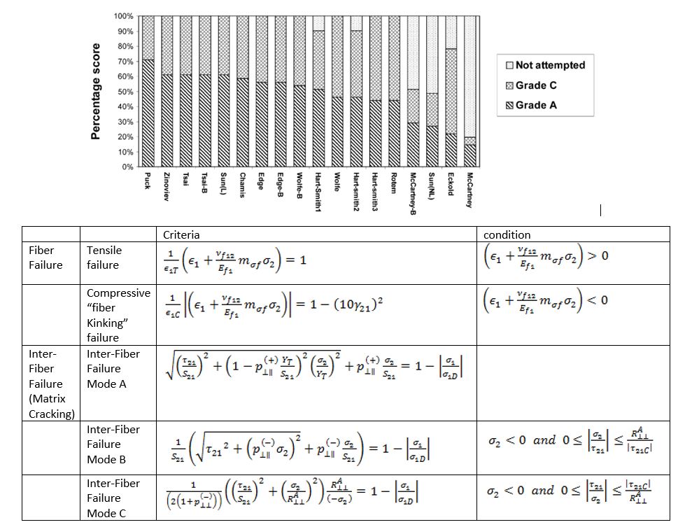
In 2002, Kaddour and Hinton, because none of the failure and damage criteria and theories were credible for practical engineering applications, tried to find the best criteria with a global call to ” The world wide failure exercise (WWFE) “to establish a benchmark for failure criteria.

In this blog, I try to review the valid failure criteria related to composite materials that have been entered into Abaqus and LS Dyna finite element software so far. Only the criteria of intra-laminar failure of composites are examined. In future articles, I will write about interlaminar failure criteria.

Damage and failure Analysis for FRP Composites: methods

In total, there are four methods for modeling damage in composite materials:

1- Fracture Mechanics

The fracture mechanics method tends to predict the initiation and growth of damage. In this method, the strain rate at the tip of the crack, whose size is known, is compared with the critical values (critical strain energy loss rate), to determine the energy required to produce a new crack surface. This method can be used to measure residual compressive strength and delamination growth in composites. The disadvantage of using this method is the uncertainty of the crack size and location.

2- Plasticity method

The plasticity method is used for composite materials that have plastic behavior (such as boron/aluminum, graphite/Peak, and thermoplastic composites). This method can be combined with the degradation criterion and predict the damage.

3- failure criterion

The failure criterion method is generally divided into two categories:

a) interaction and

b) non-interaction.

Non-interaction failure criterion is based on the assumption that different damage modes are not dependent on each other and an expression can be expressed for each damage mechanism. For example, the criteria of maximum stress and maximum strain are of this type. The stress criterion is defined in such a way that the stress in any direction of the material should not exceed the strength value of that direction and the strain should not exceed the failure strain.

On the other hand, interaction failure criteria are based on the assumption that two or more failure mechanisms interact. They also define a failure level in the space of stress or strain. This level of failure is usually a polynomial based on stress or strain and shows a failure envelope. Any point within this failure range means no failure. Tsai-Wu, Tsai-Hill, and Hoffman criteria are among these criteria. But the disadvantage of these failure criteria is not expressing the damage mechanism. As a result, their modified types are used to distinguish between failure modes. The disadvantage of using this method in composites is that it cannot show the size and location of the crack, and for this reason, the fracture mechanics method is better than this method. Also, this method is related to static analysis and is used for uniaxial composites.

4- Continuum Damage Mechanics (CDM)

The HICAS project was the first research project of the European Union from 1998 to 2000. One of the goals of this project was to find the appropriate failure model to apply in explicit finite element codes. The method that was finally accepted was the continuum damage mechanics.

The continuum damage mechanics method can predict all types of damage modes and allows the mechanical behavior of the material to be time-dependent and irreversible under mechanical loads. The advantage of this method is that it can be easily combined with the failure criteria based on stress and strain and predict the initiation of damage, and combined with the fracture mechanics method to model the growth of damage by coupling internal damage variables and fracture energy.

Continuum damage mechanics was first developed by Kachanov to model creep failure. This method models defects in the composite material and their growth on a macroscopic scale. Defects in composite materials are first formed on a micron scale, but analyzing the model of large micron-scale structures is inefficient. For the connection between micro and macro scales, it is suggested to use the medium (meso) scale based on continuum damage mechanics.

In the continuum damage mechanics method, the damage effect in the material is defined by effective stress and effective strain. the damage reduces the properties of the material. There are two modes of tensile and compressive damage for each fiber direction and its two transverse directions. It is assumed that tensile and compressive damage modes are mutually influencing; So, a mode is considered for each direction and one damage variable.

Based on observations, it has been determined that crack growth and failure of a material depend on the behavior of the material in tension. This behavior depends on the formation of micro-cracks in which it is formed. With the beginning of stretching, these cracks are formed in different parts of the material. But if at some point, the tensile stress reaches the strength of the material, a double deformation caused by micro-cracks can be seen in one area. This area is called the fracture area. In this area, the strain increases with the gradual reduction of the tension. This phenomenon is called strain softening.

In this case, the tangential stiffness becomes negative. The strain localization in finite element analysis causes strain concentration and mesh sensitivity. There are several distinct methods to avoid mesh sensitivity problems:

1- Modeling using the nonlocal smeared cracking

2- Definition of the Gradian-dependent material

3- Micropolar continuum theory

4- Viscosity adjustment

5- Local manipulation of material properties depending on the element size

Gradian-dependent and micropolar theory methods require finite element programming. Also, viscosity adjustment is not used for brittle materials.

In composite materials, damage can be defined in two ways:

  1. reduction of material properties
  2. reduction of elastic strain.

In the continuum damage mechanics method, a material with micron defects can be considered homogeneous. So, the damage growth is defined by the average stress or strain. But since many defects such as porosity, microcracks, and internal stresses are usually formed in the manufacturing process of composites, simulating damage on a microscopic scale will be very complicated due to the local changes in strength caused by the mentioned defects. to consider the changes in the strength of the composite material, some researchers assume the damage variable as a form of Weibull distribution and predict the damage growth with it.

Failure Criteria for FRP Composites

To examine damage analyses such as impact, a failure criterion is used to determine the initiation of damage. Fiber-reinforced composite materials have several damage modes, each mode has its failure criterion. Various failure criteria have been proposed for composite materials; But until now, there is no suitable failure criterion to make an accurate prediction when the stress distribution is complex (such as the impact process).

The need to predict the failure of composites has led to many theories in this field. Most of the criteria are based on stress and are in the form of an equation or a set of equations. The classification of FRP composite failure criteria is not based on a single criterion. Based on the classification done by Echabi and Paris the failure criteria are divided into two categories:

  • physical basis (related to failure modes) and
  • non-physical basis (not related to failure modes).

non-physical basis criteria are expressed using a mathematical relationship and generally in a polynomial form and predict failure by interpolating from several experimental results. In this type of criteria, there is no attempt to specify the location or modes of failure.

Non-physical failure criteria are generally expressed in quadratic polynomial form and in-plane stress mode as eq. 1. In the mentioned equation, F_ij and F_j according to the selected criteria and when f=1, failure occurs:

Abaqus & LS-Dyna failure Criteria Material Models

So far, seven failure criteria for unidirectional fiber composites have been added in Abaqus. six of them are directly accessible from the Abaqus material models library in the Abaqus/ CAE environment and only the LaRC05 criterion is required to be added to the model through the edit keyword or *.inp file. Also, one criterion for fabric materials and two failure criteria for unidirectional laminated composites can be used by subroutines.

In LS Dyna, there are 8 material cards for predicting the failure of uni-directional FRP composite materials, which are reviewed below.

Non-physical-based failure criteria

Tsai-Hill failure criteria

In the Tsai-Hill failure criterion, the coefficients are expressed according to relations eq. 1. according to whether the stress is tensile or compressive. It should be noted that being tensile or compressive is effective in determining the strength in the direction of the fiber or perpendicular to it. In these equations, X_t, X_c, Y_t, and Y_c are the tensile and compressive strength in the direction of the fiber and perpendicular to it, respectively.

Abaqus has set this criterion as failure measures, and it is used for plane stress states and does not consider any material degradation.

Tsai-Wu failure criteria

In the Tsai-Wu criterion, the coefficients of equation 1 are determined according to equation 3. It should be mentioned that -1≤〖F^*〗_12≤1 and it is determined based on experimental tests.

The Tsai-Wu criterion has physical inaccuracy and cannot give correct results in all loading cases, and the FEA project engineer should pay attention to it. For example, to predict loading failure under tensile biaxial stress, the results depend on compressive failure stress, which is physically unacceptable.

The Tsai-Wu criterion was written in terms of a polynomial of infinitesimal strains which is another drawback of the Tsai-Wu failure criterion.

The Tsai-Wu criterion can be used with some changes along with the Chang-Chang failure criterion in the *MAT_055 material model for the tensile and compressive modes of the matrix in LS Dyna.

Azzi-Tsai-Hill theory

The Azzi-Tsai-Hill failure theory is the same as the Tsai-Hill theory, except that the absolute value of the cross-product term is taken:

Hoffman failure criteria

Hoffman used the same coefficients as the Tsai-Wu criterion in a separate criterion. The only difference between his criterion and Tsai-Wu’s criterion is the definition of F_12 coefficient in the form of the equation:

Hoffman failure criterion is not available in Abaqus and LS Dyna software.

Physically based criteria

In the following, damage material models of physical basis criteria are introduced. Physically based failure criteria separate failure modes from each other. These criteria are not always uniform and have peaks that generally express the change in the failure mode.

Maximum stress/strain failure criteria

Maximum strain and maximum stress failure criteria are almost the simplest physical base failure criteria. In the maximum strain criterion, failure works by checking when the failure strain is satisfied. This criterion is defined according to the equation ——. In these equations, ε_1^o, ε_2^o, and ε_12^o are respectively the failure strains in tension and compression in the direction of the fiber and perpendicular to it:


The maximum stress failure criterion is similar to the maximum strain criterion, with the difference that the corresponding stresses are placed instead of the strains in the relation —-. This criterion can be written as equation —:

In this relationship, X, Y, and S_12 are the strength in the longitudinal, transverse, and shear directions of the composite.

Chang-Chang Failure Criterion

Chang-Chang material model can be used through *MAT_022 and the modified version through *MAT_054 / *MAT_ENHANCED_COMPOSITE_DAMAGE in LS Dyna. In criterion *MAT_022 material model, the ratio of shear stress to shear strength is defined, which is proposed to separate fiber and matrix failure criteria. This ratio is defined by Chang-Chang to add the nonlinear shear effect in the failure criterion equations.

Chang-Lessard Failure Criteria

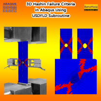
Chang-Lessard failure criterion can be used with USDFLD & VUSDFLD subroutines for analysis in standard and explicit Abaqus solvers from example 1.1.14 Abaqus Example Problem Guide are available.

Matrix compression failure criterion has the same form as that for matrix tensile cracking, since the previous two failure mechanisms cannot occur simultaneously at the same point. After the failure index exceeds 1.0, both the transverse stiffness and Poisson’s ratio of the ply drop to zero.

It was evident that, unless the shear stress vanishes exactly, fiber-matrix shearing failure occurs before fiber buckling. However, fiber buckling may follow after fiber shearing because only the shear stiffness degrades after fiber-matrix shearing failure. Fiber buckling in a layer is a catastrophic mode of failure. Hence, after this failure index exceeds 1.0, it is assumed that the material at this point can no longer support any loads.

Chang and Lessard assume that after the failure occurs, the stresses in the failed directions drop to zero immediately, which corresponds to brittle failure with no energy absorption. This kind of failure model usually leads to immediate, unstable failure of the composite. This assumption is not very realistic: in reality, the stress-carrying capacity degrades gradually with increasing strain after the failure occurs. Hence, the behavior of the composite after the onset of failure is not likely to be captured well by this model. Moreover, the instantaneous loss of stress-carrying capacity also makes the post-failure analysis results strongly dependent on the refinement of the finite element mesh and the finite element type used.

Feng Failure Criterion

The Feng failure criterion which is available in the LS Dyna material library under the *MAT_021 card is driven from the finite deformation theory and applies to both finite deformation theory and infinitesimal strain theory. Since the formulation of this criterion is written based on finite strain invariants, unlike the Tsai-Wu criterion, it can be used in finite strain analyses. Also, this criterion can separate the two damage modes of fiber and matrix, which the Tsai-Wu criterion could not do.

Hashin FRP composite failure criteria

Hashin and Rotem believed that due to the different nature of fibers from the matrix, their failure should be investigated separately. The work of Hashin and Rotem and after that, the work of Hashin was based on this assumption.

This criterion is formulated for both two dimensions and three dimensions. The three-dimensional formulation of this criterion is given in Table —.

The weakness of the Hashin failure criterion is the lack of correct prediction of the beginning of failure when transverse compressive loading and shear loading are applied. For this reason, in many papers, instead of its transverse and shear stress mode, transverse and shear stress modes of other criteria such as Puck failure criteria, maximum stress, and maximum strain have been used. If only the Hashin damage initiation is defined in the analysis model, the initiation criteria will affect only output. However, unlike the failure theories like Tsai-Wu, here an associated evolution law can be supplied to model the damage process. Damage evolution is based on energy dissipation and includes the removal of elements from the mesh. In LS Dyna, *MAT_162 / *MAT_COMPOSITE_MSC is a criterion similar to Hashin failure criteria in Abaqus, but the Hashin damage initiation criterion of 1980 has been added with some changes to improve the effect of highly constrained pressure on composite failure. Also, the MLT model developed by Matzenmiller et al.(1995), and then improved by Yen (2002), is used for the post-failure behavior of the composite. This damage model code was developed by Materials Sciences Corporation and an additional license from this company is required for use.

Yamada-Sun

After the proposal of the Hashin-Rotem criterion and its publication, other criteria were proposed on this basis; For example, Yamada and Sun proposed a failure criterion for the fiber mode that causes effects on the in-plane shear strength. This criterion was then used by Chang to predict the failure mode in LS DYNA.

Christiansen failure criterion

Christiansen presented a criterion for fiber and matrix failure modes that included the effect of hydrostatic pressure. Christensen made great efforts to provide a suitable criterion for predicting the failure of composite materials. Christiansen failure criterion is not used in Abaqus and LS Dyna.

Hart-Smith criterion

After Christiansen, Hart-Smith proposed a failure criterion based on the maximum shear stress criterion along with auxiliary rules. He presented his theory for the failure of polymer matrix fiber composites based on the maximum shear stress criterion. His criterion was first extended for isotropic materials and then for laminated orthotropic materials (fiber-reinforced composites). This damage model does not exist in Abaqus and LS Dyna.

Puck composite failure criteria

Like Hashin, Puck also believed in the separate investigation of fiber and matrix failure. This criterion has inspired many failure composite material models.

Based on the rating of The World-Wide Failure Exercise II (WWFE-II), among the failure criteria presented in this exercise, the Puck criterion has the most agreement with the laboratory results.

For more information about these criteria and information about the mechanical properties and coefficients used in the above equations, refer to Puck’s papers.

In Abaqus, only the matrix mode of the Puck criterion is used in the UniFiber VUMAT subroutine (Download), and this criterion is not fully used in any of the existing Abaqus material models.

In LS Dyna, only the inter-fiber failure mode is used in Pinho and Camanho material damage models through MAT_261 and MAT_262  material cards.

LaRC05 FRP composite failure criteria

the LaRC05 composite failure criterion is introduced in Abaqus/Standard 2017. This failure criterion is intended for laminated polymeric-matrix fiber-reinforced composites consisting of unidirectional plies and has been implemented in the form of two built-in user subroutines:

  • a built-in UVARM user subroutine that evaluates the LaRC05 damage criterion and provides the output of damage tolerance. The option is available for both 2D and 3D stress states.
  • a built-in damage initiation UDMGINI user routine that can be used with XFEM-enriched elements to evaluate the onset of crack initiation and propagation. It is available only for 3D stress states and the family of three-dimensional stress-displacement continuum elements for which XFEM is supported.

An adaptation of the Mohr-Coulomb failure criterion for unidirectional composite plies is used for matrix cracking failure.

Because Pinho and Camanho are the main developers of the LaRC05 failure criteria, I will explain here the separate criteria that are based on the LaRC05 failure criteria. *MAT_LAMINATED_FRACTURE_DAIMLER_PINHO / *MAT_261 was developed by Pinho, Iannucci & Robinson (2006) and *MAT_262 was developed by Maimi, Camanho, Mayugo & Davila (2007) can be use in LS-Dyna. These two criteria are continuous and physical damage models and consider nonlinear in-plane shear behavior.

Stress or strain Failure Criteria?!

Perhaps the biggest question in the field of failure criteria is whether to express them in terms of stress or strain. This question goes back a long time ago and since the beginning of the definition of failure criteria and continues until now. For example, some aerospace organizations define the design process based on stress and others based on strain. A favorable conclusion has not yet been reached regarding the superiority of one over the other, and it is not possible to speak with certainty about the superiority of one and the weakness of the other.

The most common failure criterion is von Mises, which is defined based on stress. Other criteria that are constantly used are the maximum shear stress (Tresca) criterion, the maximum normal stress criterion, the maximum normal strain criterion, and criteria developed from the mentioned items that can be based on stress or strain. Mises criterion can be used for isotropic materials and there are unpredictable complications in it. Mises criterion can be written both in terms of stress and strain. The interesting point is that in this case there is no difference between the criterion based on stress and the criterion based on its strain.

There is the fact that all criteria can be written in terms of both strain and stress. But Mises criterion can only be used for ductile metals and it will have a huge error for other materials. All these differences between stress-based criteria and strain-based criteria come from the tensor nature of stress and strain.

Christiansen believes that failure criteria should be written with tensor terms. Especially if this criterion is supposed to be used to simulate fracture mechanics in brittle materials as well as dynamics of dislocations in deformable materials.

The difference in criteria based on stress and strain becomes more interesting when the time variable foot is opened to the problem; It means that the behavior of material depends on time. For example, during a constant loading (tension) that may last for a long time (sometimes up to several years), failure occurs at some points, which is called creep failure. On the other hand, if constant strain loading is used for a long time, which is called relaxation, no damage will be observed. The relaxation means failure in constant strain on a molecular scale. Therefore, failure criteria based on stress instead of strain are used in such problems.

Another advantage of stress-strain-based criteria is that they can be applied to both solids and fluids. Deformation and strain have no meaning for fluids. Some viscoelastic fluids can degrade. Inevitably, stress terms should be used in such cases.

Selection Guide

LS-Dyna FRP Composite Failure Criteria

Table 1 LS-Dyna FRP Composite Damage Models

Material damage modelElementFailure criteriaComments
*MAT_021 MAT_ORTHOTROPIC_THERMALShell, Tshell, SolidFeng failure criterialinearly elastic, orthotropic material with orthotropic thermal expansion finite displacement and rotations as long as the small strains a
*MAT_022 COMPOSITE_DAMAGEShell, Tshell, SolidChang-ChangNo fiber compression failure Simple brittle model No crash front algorithm
*MAT_054/55 ENHANCED_COMPOSITE_DAMAGEShell, Tshell, Solid54: Chang-Chang 55: fiber: Chang-Chang matrix: Tsai-Wu  Improvement of MAT_022 Crash front algorithm Minimum stress limit factor
*MAT_058 LAMINATED_COMPOSITE FABRIC  Shell, Tshell (1,2)Modified Hashin. Three different failure criteria: 1. multi-surface, 2. smooth failure surface, 3. faceted failureFor fabrics Smooth stress-strain relation Non-linear shear behavior Minimum stress limit factor Exponential softening
*MAT_059 COMPOSITE_FAILURE_MODELShell, Tshell, Solid, SPHModified HashinSimilar to MAT_054 Crash front algorithm Minimum stress limit factor
*MAT_158 RATE_SENSITIVE_COMPOSITE_FABRICShell, TshellModified HashinFor fabrics Same as MAT_058 Rate sensitive
*MAT_261 LAMINATED_FRACTURE_DAIMLER_PINHOShell, Tshell, SolidPinho: Considers the state of the art Puck’s criterion for inter-fiber failurePhysical-based failure criteria Continuum damage model Linear softening evolution based on fracture toughness
*MAT_262 LAMINATED_FRACTURE_DAIMLER_CAMANHOShell, Tshell, SolidCamanho: Considers the state of the art Puck’s criterion for inter-fiber failurePhysical-based failure criteria Continuum damage model Bi-linear/linear softening evolution based on fracture toughness

Table 2 Abaqus FRP Composite Damage Models

Abaqus FRP Composite Failure Criteria

Material damage modelElementFailure criteriaComments
Plane Stress Orthotropic Failure Measuresplane stress, shell, membraneStress-based: Maximum stress theory Tsai-Hill theory Tsai-Wu theory Azzi-Tsai-Hill theory   Strain-based: Maximum strain theoryNo softening evolution
Hashin Damageplane stress, shell, continuum shell, and membrane elementsDamage initiation: Hashin and Rotem, 1973, Hashin, 1980   damage evolution: Matzenmiller et. al (1995) and Camanho and Davila (2002).Physical-based failure criteria Continuum damage model Linear Progressive degradation of material stiffness Softening evolution based on energy dissipation
LaRC05three-dimensional solid, plane stress, shell, solid shell, and membrane elementsDamage initiation: Pinho et al. (2012) Damage evolution: Only for XFEM analysisSince Abaqus2017 Available only in Abaqus/Standard
Chang-LessardCPS4 & CPS4RDamage initiation: Chang and Lessard (1991)   Damage evolution: Instantaneously drops to zero.USDFLD & VUSDFLD through Abaqus Examples. Four modes of failure. Brittle failure with no energy absorption
Fabric Reinforced CompositesShell (S4R and S3R), continuum shell (SC6R and SC8R), plane stress (CPS family), and membrane (M3D family) elements. not supported in ABAQUS/Explicit for small-strain shell elements (S4RS)Johnson, 2001 and Sokolinsky et al., 2011Bidirectional fabric-reinforced composites. Available only in Abaqus/Explicit. progressive stiffness degradation due to fiber/matrix cracking, and plastic deformation under shear loading. Softening evolution based on fracture energy per unit area.  
UniFiber VUMATthree-dimensional stress-displacement continuum elements (C3D4, C3D6, C3D8R, C3D10M)Damage initiation: Hashin, 1980 For the matrix material Puck, 1998   Damage evolution: Instantaneously drops to zero.Accessible through the VUMAT subroutine. Available only in Abaqus/Explicit. No softening evolution.
0 0 votes
Article Rating
Subscribe
Notify of
guest
0 Comments
Inline Feedbacks
View all comments