
 View Large
Optimal Design of Filament-Wound Composite Pressure Vessels – Type IV
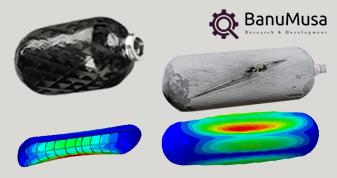
Filament-Wound Composite Pressure Vessels have a very complex design process. it is high-tech in today’s industries. There are several methods for filament winding on cylindrical, spherical, and annular containers. In this case study, composite overwrapped pressure vessels were designed and simulated in finite element analysis software. There are several standards for the design of pressure vessels, the most famous of which is ASME X. In addition, the DNV standard is used when necessary.
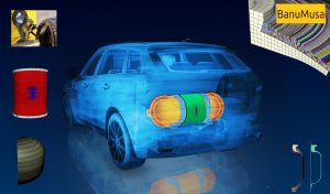
Engineering design of composite-overwrapped pressure vessel
What are Type IV composite pressure vessels?
Type IV composite pressure vessels are high-pressure tanks made of fiber-reinforced composite materials. They are defined by the following characteristics:
- Manufactured using the filament winding process – Continuous fibers such as glass, carbon, or aramid are wound around a mandrel at various angles to form the tank. This allows for optimizing fiber orientations for strength.
- Reinforced polymer matrix – The continuous fibers are embedded in a thermosetting polymer matrix such as epoxy or vinyl ester resin. The matrix binds the fibers and transfers loads.
- Operating pressures above 250 psi – Type IV vessels are designed to operate at pressures above 250 psi, up to several thousand psi.
- Hoop-winding dominant – The majority of fibers are wound in the hoop direction around the cylinder to carry the high hoop stresses during pressurization.
- Structural – The vessels primarily rely on the strength of their composite laminate structure for pressure retention, rather than a metal liner.
- Used for high-pressure gas storage – Common applications include storing compressed natural gas, oxygen, nitrogen, hydrogen, and helium.
- Higher strength-to-weight ratio – Compared to metallic pressure vessels, composites provide a higher strength-to-weight ratio due to their high fiber volume fractions. This allows for lighter-weight vessels.
- Glass or carbon fiber reinforced – Glass and carbon are the most common fiber reinforcements used, though aramid and basalt are also options.
Simulation-Driven Product Development of Type IV Filament-Wound Composite Pressure Vessels
Here are some ways simulation-driven product development can help optimize Type IV filament-wound composite pressure vessels:
- Predict Strength and Failure – Finite element analysis (FEA) simulations can predict the hoop and axial stresses in the vessel wall under internal pressure loads. Failure criteria can identify risks of fiber fracture, delamination, or buckling failure.
- Analyze Stress Concentrations – Locations with stress concentrations due to geometrical discontinuities can be identified through simulations. These risks can be mitigated in the design.
- Optimize Fiber Angles – Parametric studies in the simulations, varying fiber winding angles and layer sequences, can determine the combination that provides the highest strength and stiffness.
- Reduce Weight – Simulations can evaluate the effect of reducing the laminate thickness and fiber volume fraction on strength. This helps minimize weight without compromising safety factors.
- Size Components Correctly – The simulations can size vessel end caps, fittings, and reinforcements to ensure adequate strength margins and minimize weight.
- Verify Burst Pressure Rating – Nonlinear simulations with realistic pressure loads can verify if the design meets the required burst pressure rating with adequate safety factors.
- Predict Fatigue Life – Progressive damage modeling in the simulations can predict the fatigue life of the vessel under cyclic pressure loads. This helps determine inspection and replacement needs.
- Validate Prototypes – Initial physical test results of prototypes can be used to calibrate and validate the simulation models. Refined models reduce the need for physical testing.
In summary, the simulation-driven design enables optimal sizing and layout of Type IV filament-wound composite pressure vessels through virtual testing, optimization, failure analysis, and validation – reducing physical prototypes, testing costs, and shortening development time.
Abaqus & WCM Plugin for Composite Pressure Vessels
Simulation-driven product development of Type IV filament-wound composite pressure vessels with the Wound Composite Modelling (WCM) Abaqus plugin can help manufacturers in several ways:
- Improved modeling accuracy:
The WCM Abaqus plugin enables manufacturers to model the winding process of filament-wound composite pressure vessels more accurately. This can lead to more precise simulation results, which can help optimize the design and performance of the product. - Reduced simulation time:
The WCM Abaqus plugin can significantly reduce the time required to perform simulations of filament-wound composite pressure vessels. This can help manufacturers to iterate their designs more quickly and bring products to market faster. - Enhanced design optimization:
The WCM Abaqus plugin can help manufacturers optimize their designs by simulating the effect of different winding patterns and fiber orientations. This can help to identify the most effective design parameters for a given application. - Improved product performance:
Simulation-driven product development with the WCM Abaqus plugin can help manufacturers to optimize the performance of their products by simulating the behavior of composite materials under different operating conditions. This can help to improve the durability, reliability, and safety of the product. - Reduced development costs:
By using the WCM Abaqus plugin, manufacturers can reduce the number of physical prototypes needed to validate the design of their products. This can help to save time and money during the product development process.
Design-by-Analysis – ASME X & COPVs
Simulation-driven product development of Type IV filament-wound composite pressure vessels with ASME X refers to using the ASME Boiler and Pressure Vessel Code, Section X, to design and analyze these vessels.
The ASME X code provides guidelines and rules for the design, fabrication, and inspection of fiber-reinforced plastic (FRP) vessels, including Type IV filament-wound composite pressure vessels. By using the ASME X code in simulation-driven product development, manufacturers can ensure that their products meet the required safety and performance standards.
Design-by-analysis using ASME X for Composite Overwrapped Pressure Vessels (COPVs) involves using finite element analysis (FEA) to determine the stress and deflection in the vessel under various loading conditions. The ASME X code provides guidelines for the design and analysis of high-pressure vessels, including COPVs made of composite materials.
Here are some steps involved in design by analysis using ASME X for COPVs:
- Determine the load conditions:
The first step in design by analysis is to define the load conditions that the COPV will be subjected to during its service life. This includes internal pressure, external loads, and thermal loads. - Select the material properties:
The next step is to select the appropriate material properties for the composite material used in the COPV. This includes the modulus of elasticity, Poisson’s ratio, and ultimate strength. - Create a finite element model:
Using the load conditions and material properties, a finite element model of the COPV is created. The model includes the geometry, boundary conditions, and material properties. - Perform the analysis:
The next step is to perform the analysis using the finite element model. This involves applying the load conditions and calculating the stress and deflection in the COPV. - Evaluate the results:
The results of the analysis are evaluated against the design criteria specified in the ASME X code. This includes checking for stress limits, deflection limits, and fatigue life. - Optimize the design:
If the analysis results do not meet the design criteria, the design is optimized by adjusting the geometry, material properties, or boundary conditions and repeating the analysis. - Validate the design:
Once the design meets the design criteria, the COPV is manufactured and tested to validate the design.
Steps
- Design-by-Analysis (ASME sec X)
- Lay-up definition
- Static and Dynamic burst pressure
- Thermal Expansion
- Dynamic drop tests and impacts
- Cyclic and fatigue assessment
- Parametric design
- Design of Experiment
- Optimum design
COPV weight optimization capabilities allow up to a 30% reduction of the composite mass.
Are you interested? please contact us
Abaqus Tutorial: LaRC05 Failure Criterion For Fiber-Reinforced Composites
This comprehensive course provides a thorough understanding of the LaRC05 failure criterion for fiber-reinforced composites. Participants will delve into the theory behind the LaRC05 criterion and its significance in predicting failure behavior in these materials. Through practical implementation using the Abaqus software, students will learn how to characterize material properties, validate and verify simulations, and apply the LaRC05 criterion to solve real-world engineering problems. By the end of the course, participants will have gained the knowledge and skills necessary to confidently utilize the LaRC05 failure criterion for accurate analysis and design of fiber-reinforced composites.
Abaqus tutorial video (*.mp4)
Lecture notes (PDF)
Abaqus workshop files (*.cae, *.inp, *.jnl, *.odb)
15-day money-back guarantee
Free 24/7 online mentoring
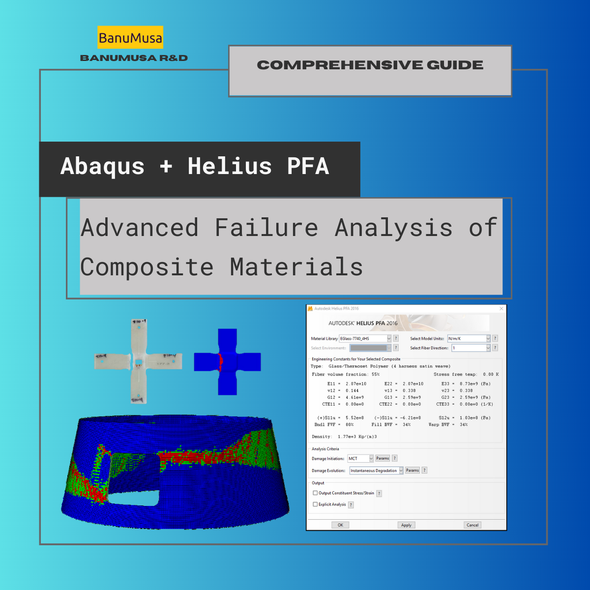
Advanced Failure Analysis of Composite Materials with Abaqus and Autodesk Helius PFA: A Comprehensive Guide
The "Advanced Failure Analysis of Composite Materials with Abaqus and Autodesk Helius PFA: A Comprehensive Guide" online course is designed to teach engineers, technicians, and researchers advanced analysis techniques for composite materials. The course covers a range of topics, including material modeling, failure criteria, damage mechanics, progressive failure analysis of composites, and fatigue.
Participants will learn how to use Abaqus and Autodesk Helius PFA software to model, simulate, and analyze composite materials under different loading conditions. The course is divided into several modules, each covering a different aspect of composite material analysis. The course provides an excellent opportunity for engineers and researchers to expand their knowledge of advanced analysis techniques for composite materials and gain hands-on experience with industry-standard software tools.
Abaqus tutorial video (*.mp4)
Lecture notes (PDF)
Abaqus workshop files (*.k, d3plot)
15-day money-back guarantee
Free 24/7 online mentoring
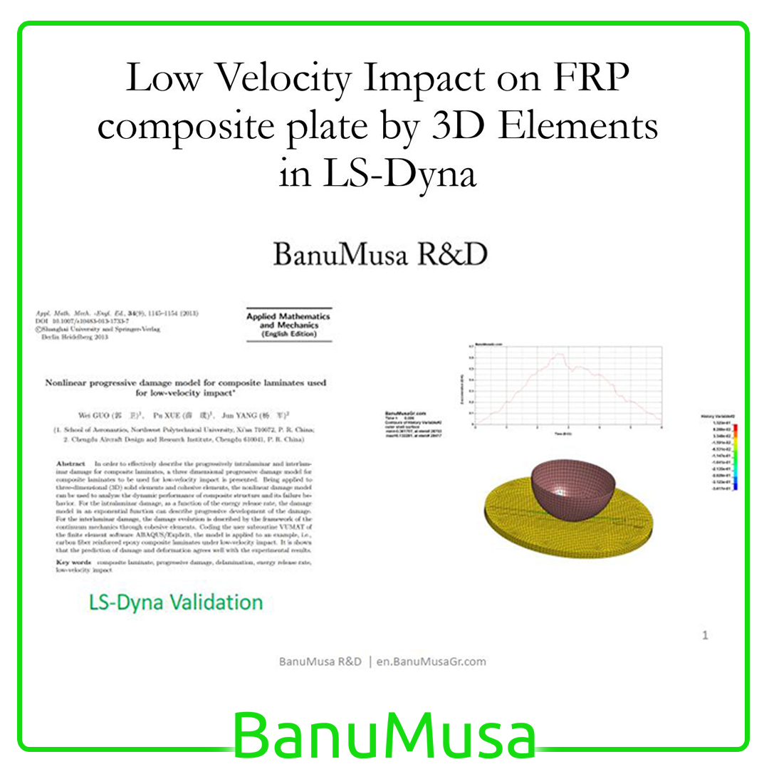
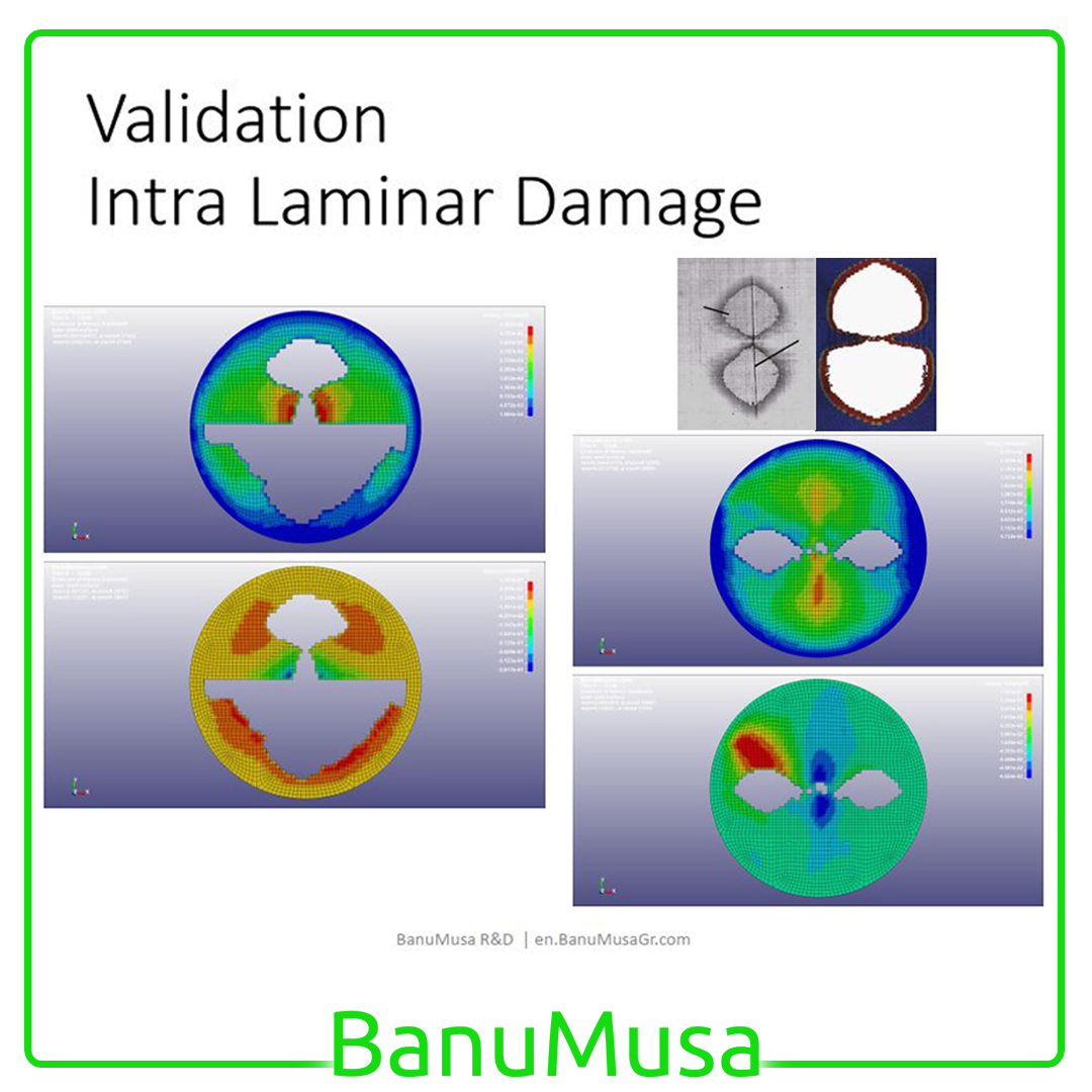
LS-Dyna Tutorial: 3D modeling techniques for low-velocity impact analysis of FRP composite laminate
In this LS-Dyna tutorial video, we have tried to cover all the tips and tricks that are required by the user when modeling low-velocity impact FRP laminates FEA analysis with LS-Dyna. Material models for FRP composite & cohesive materials are available in the LS-Dyna and its parameters are described. Also, the modeling methods of geometry, FRP material, cohesive, contacts &, etc. are explained one by one. Finally, in a comprehensive example, the LS-Dyna finite element model is validated by Guo et al. (2013) paper. All the modeling & results files, as well as the LS-Dyna tutorial video, are included in this package.
LS-Dyna tutorial video (*.mp4)
Lecture notes (PDF)
LS-Dyna workshop files (*.k, d3plot)
15-day money-back guarantee
Free 24/7 online mentoring
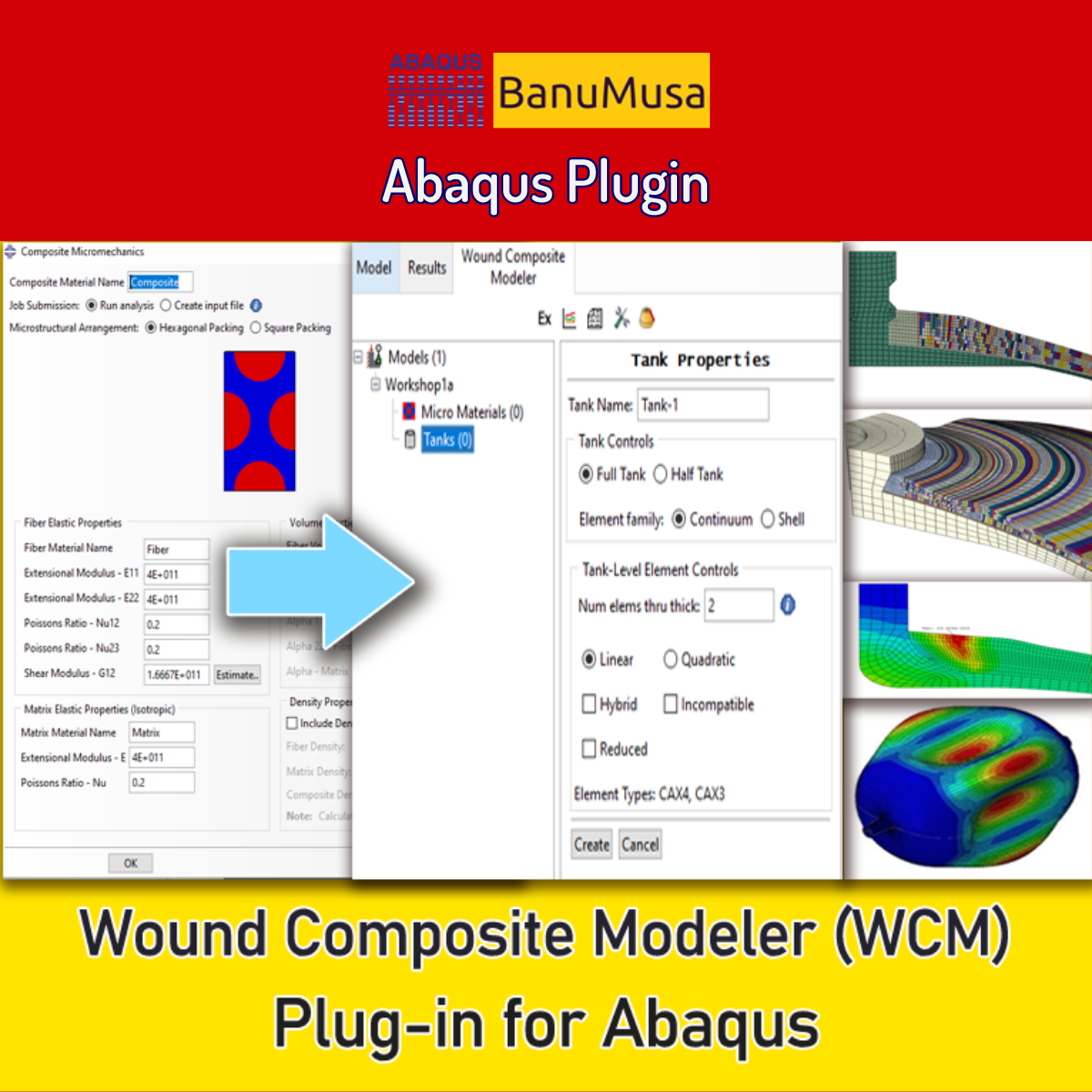
Wound Composite Modeler Plugin for Abaqus
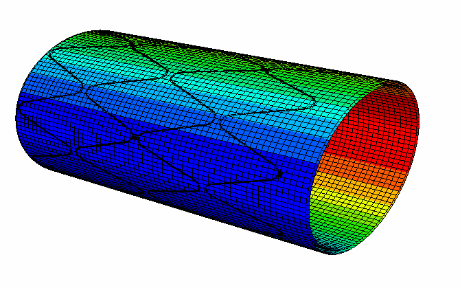
Engineering experts at SIMULIA have developed the Wound Composite Modeler plugin for Abaqus FEA software that enables the modeling of spatial variation of fiber orientation in a practical way. Because of the development of the use of composite materials and its widespread use in the manufacturing of pressure vessels by the filament winding method, the complexity of the design and analysis of these vessels prompted engineers to develop a tool for this purpose to increase the speed and accuracy of the design. Now, the WCM plugin (Ver. 2016) with extensive features is available.
Documentation (PDF + HTML)
Abaqus plugin files (*.RAR)
Abaqus workshop files
15-day money-back guarantee
Free 24/7 online mentoring