 View Large
Contact Stress in Rail Joint Region
The growth of fatigue and surface cracks due to impact and frequent contact stress in rail joint regions has been the cause of many rail damages and losses in recent years. In addition, the noise and vibrations on the wagon due to the impact from the wheel in the region of the rail joint led to the discomfort of passengers.
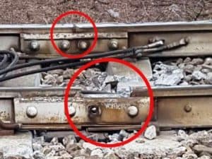
On 25 January 2018, the Pioltello train derailment was due to a broken rail joint region. 3 women have been killed.
Rail Joint Region Design Consideration
There are a few factors to consider regarding fatigue, impact, and contact stress in the rail joint region:
- Fatigue – The rail joint is a point of discontinuity where stresses can concentrate. This can lead to higher stresses and fatigue damage compared to mid-rail locations. Repeated wheel impacts at the joint can cause gradual crack initiation and propagation over time. Rail joint designs aim to minimize stress concentrations and provide adequate clamping force to mitigate fatigue.
- Impact – When wheels pass over the rail joint, there is a slight impact force due to the height difference between the two rail sections. This impact force generates dynamic stresses that contribute to fatigue damage. Specialty rail joint designs use elastic elements to absorb some of the impact energy and reduce forces transmitted to the rail.
- Contact stress – As wheels pass over the joint, there is a momentary increase in contact stress between the wheel and rail. This is due to the change in the rail profile at the joint. High contact stress can accelerate the wear of both the wheel tread and railhead. Certain rail joint designs incorporate elastic packing layers to distribute contact stress over a wider area.
- Rail joint maintenance – The rail joint must be periodically inspected, lubricated, tightened, and adjusted to maintain proper performance. Neglecting maintenance can accelerate deterioration and lead to more severe impacts, higher stresses, and premature failure.
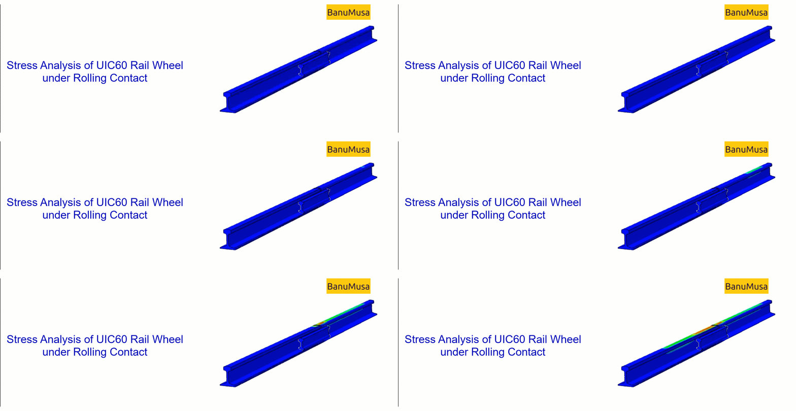
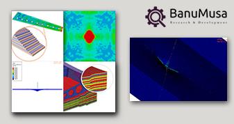
In this FEA project, to reduce the growth of fatigue and surface cracks in the joint rail region and passenger comfort, the parameters of axial force, speed, span, and joint angle were examined. These parameters have been done according to the rail profile used in the Iranian industry UIC60 and S1002 and the UIC 864-8 standard fish plate.
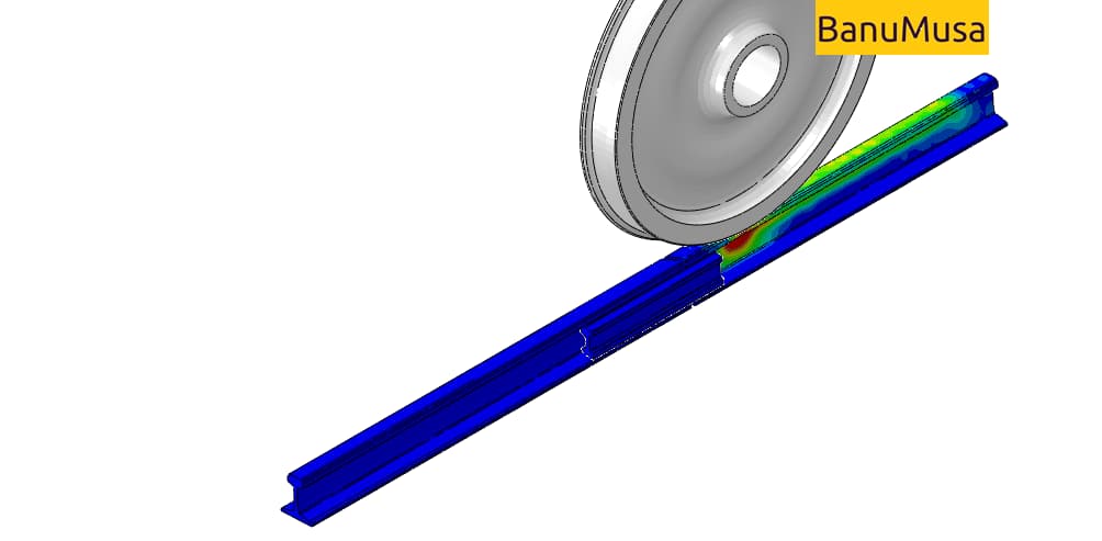
Simulation of wheel movement on rails and investigation of impact and surface stresses in the region of rail joints.
One of the types of connecting two rails (especially in the design of an interlocking system) with a certain length is the use of connecting rods. The joint method is such that two rails and two fish plates are connected with 4 or 6 bolts.
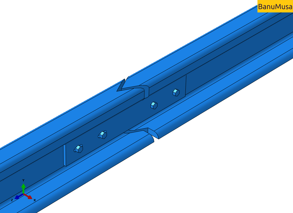
Investigation of the effect of rail joint gap angle on the distribution of contact and impact stresses
The results show that the angle of the rail gap has a significant effect on the impact stresses and the ISF parameter.
Need consulting? contact us.
– Readiness to accept and sign a contract as a research and development ( R&D ) unit of industrial companies –
